Gravity Flow Measurement in Smaller Pipes – Application Toolkit Part 2
ISCO Flow Metering Inserts
Gravity flow measurement in smaller pipes (6 – 12 inches) can present challenges; from access, to technique and cost. With everything below grade, access tends to be the final manhole; out near the site’s perimeter. In these cases, ISCO’s Flow Metering Inserts can play an important role in our Application Toolkit.
The inserts are installed from street level, generally without having to enter the manhole. They may be used in 6″, 8″, 10″, and 12″ diameter sewers in manholes as deep as 16 feet. The inserts are coupled with a bubbler flow meter and can measure flow rates ranging from one to 640 gallons per minute with 5% accuracy.
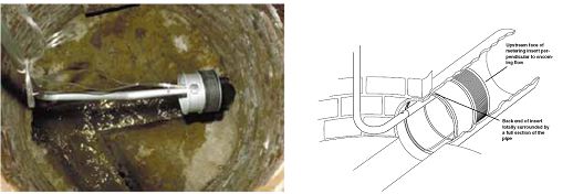
 The Flow Metering Insert consists of the metal insert with an inflatable rubber collar, a multi-section pole assembly, and a foot-powered air pump. The metering insert is a calibrated flow control section that generates an upstream head, or pressure, related to a particular flow rate in the pipe. A bubbler flow meter (ISCO 4230, Signature Bubbler) is attached to the bubble tube to since changing water level and calculate flow.
The insert is placed into the pipe invert and the bladder is filled to hold it in place and force flow thru the opening.
Multi-section poles snap together to allow installation without confined space entry. The bubble tube and bladder valve stem run up along the poles to grade
For installation, the various pieces of the insert are snapped together with enough sections of the pole to reach the bottom of the manhole. Next, with the operator at ground level, the assembly is lowered into the manhole, and the metering insert maneuvered into the entrance pipe (upstream side) of the manhole.
The metering insert is then sealed into the sewer pipe by inflating its rubber collar using the foot-powered pump and pressure gauge. The bubble line from the insert is attached to the flow meter or module, which is suspended from a rung or other means inside the manhole. The flow meter can then begin to record flow through the insert. The insert channels all flow in the sewer through the flow control section (either the round orifice or the V-notch weir).
 For lower flows, a removable V-Notch weir plate can be installed to boost water level on the low end – giving the meter better resolution. When flows are expected to fill the pipe greater than 1/3, the plate is removed and we program for ‘round orifice’.
| Calibrated Ranges |
Gallons per Minute |
Gallons per Day (Max.) |
| 6″ Flow Metering Insert | ||
| V-Notch Weir |
1 to 90 |
129,600 |
| Round Orifice |
5 to 180 |
259,200 |
| 8″ Flow Metering Insert | ||
| V-Notch Weir |
1 to 160 |
230,400 |
| Round Orifice |
10 to 320 |
460,800 |
| 10″ Flow Metering Insert | ||
| V-Notch Weir |
1 to 230 |
331,200 |
| Round Orifice |
20 to 480 |
691,200 |
| 12″ Flow Metering Insert | ||
| V-Notch Weir |
1 to 320 |
460,800 |
| Round Orifice |
40 to 640 |
921,600 |
For removal from the manhole, first release the air pressure from the inflated rubber collar. Do this by pressing the valve stem in the insert’s air supply hose, and then pulling the unit out of the pipe and lifting it from the manhole.
The inserts tend to be self-cleaning; especially the round orifice. However, on heavily solids, we’ve seen some plugging.
Another issue we face is flow metering inserts are intended to serve as a temporary installation; however, we have installed them permanently on a few occasions. Drawbacks are the bladder relaxes over time and may slide out of position; requiring re-position and keeping an eye on air pressure.
Learn More:
Visit us at www.cclynch.com or call us at 800-333-2252. Questions? Email us at info@cclynch.com.

